Video
Beyond manufacturing: Integrated services across the product lifecycle
In an earlier Flex Power Modules blog, we explored the reliability of calculated MTBF for power modules. Our conclusion was that data sheet values are only meaningful when comparing products under identical, static conditions. Even accelerated testing rarely reflects real-world application scenarios, and field return rates can vary too widely to apply universally. We also cautioned that a finite operational lifetime due to wear-out does not necessarily indicate poor reliability during that period.

In practice, power electronic modules from reputable manufacturers are highly reliable when operating under stable conditions, even at high temperatures.
Often, accelerated reliability tests performed on modules terminate without a single failure. In such cases, the accepted methodology is to assume a failure was imminent, so that at least a conservative minimum MTBF value can be calculated and declared.
Failures do occur though, and they can almost always be attributed to adverse environmental conditions. These could be shock, vibration, electrical transients, and ESD events, but in a professional application such as a data center, these effects can be identified and eliminated. However, one effect that cannot be prevented is temperature swings, which cause differential expansion and contraction of interfacing materials in the module and its terminations, and the possibility of condensation and resulting corrosion. The swings could be due to changes in ambient temperature, but the common cause is unavoidable self-heating and cooling after large load steps. Modern power converter designs can be very efficient, but customers leverage this to extract more power from smaller module form factors, so changes in dissipation and internal temperatures with load steps can still be large.
The situation is not helped by the drive to reduce average power consumption by switching processors to an ‘idle’ mode whenever possible. This approach, while effective, comes with its own set of additional complications. Sudden transitions from near-zero to hundreds of amps load and back again not only challenges a power module to maintain output voltage within specification but also generates rapid internal temperature swings that can lead to long-term mechanical stress and damage.
If all the materials within a power module — extending through its connections to the circuit board and heatsink — were homogenous, temperature swings would pose little stress. In reality, however, the materials in the thermal path in a typical module include a mix of materials such as silicon, copper, ceramic, fiberglass, aluminum, solder, and others. Encapsulant around the internal components might be present, squeezing and pulling. The materials all have differing Coefficients of Thermal Expansion (CTE), which is the ratio that a material’s linear dimension changes with temperature, usually stated in units of micrometers per meter per degree Kelvin (µm/m.K). Aluminum for example, has a CTE of about 23 µm/m·K, while at the other extreme, a silicon die has a value of about 3. For example, with a 100°C temperature change — a realistic scenario for a power semiconductor — the aluminum bond wire attachment area expands about eight times more than the silicon die beneath it. This equates to a dimensional change of approximately 2.3 µm compared to just 0.3 µm over a 1 mm length.
The latest DC/DC module power switches are often wide band-gap silicon carbide or gallium nitride types. While their CTEs are higher than silicon, around 4 and 5 respectively, at least they are closer in value to the materials they typically interface with.
For high power density DC/DCs, these switches are now almost exclusively ball-grid or land-grid array packaging, rather than traditional leaded types, which previously offered some degree of mechanical stress relief across one of the larger CTE mismatches — from lead frame through the solder to the copper traces. Through the stack of materials from the motherboard to the die and perhaps on to top-side cooling, the multiple CTE mismatches in a power module can potentially cause problems, such as microcracking or even detachment.
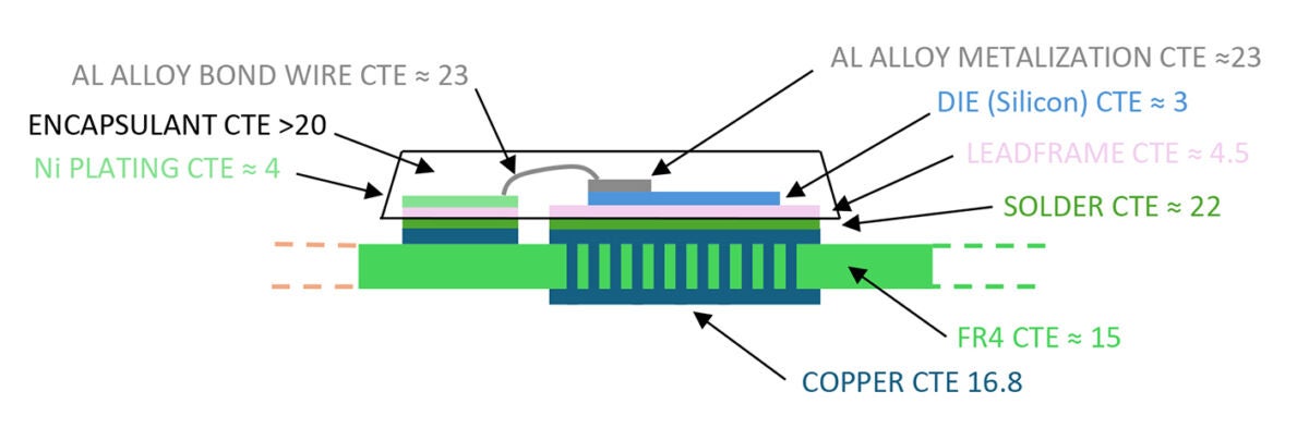
Picture: An example of a mounted power semiconductor and its multiple material CTEs
Traditionally, equipment or modules have been life-tested at constant temperatures or with controlled, repeated ambient temperature changes, typically at ramp rates of around 15°C per minute. Thermal shock tests push this further, often reaching around 40°C per minute. While such tests are standard for independent agencies, a more realistic approach is to simulate the actual end-use environment. In data center applications, for example, ambient temperatures tend to remain stable, while load levels fluctuate with defined patterns, ramp rates, and repetition. It’s clear that the thermal stress effects from this approach would be quite different from those caused by a fixed load and varying ambient temperature.
Flex Power Modules designs its power modules to minimize issues related to CTE mismatch and conducts thermal testing based on typical market conditions. However, we also collaborate closely with customers to simulate their specific application environments, enabling a more accurate and credible, real-world reliability assessment.