Product
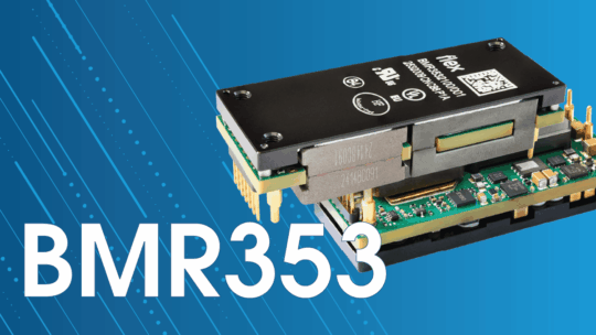
BMR353: High-power, high-efficiency eighth-brick IBC optimized for AI demands
It’s common knowledge that modern data centers require ever-increasing levels of power and efficiency, but what’s less clear is the best approach to maximizing those two metrics within a power conversion system.
Today’s market standard for embedded power system design is a two-stage 48 V-to-core rail architecture using an intermediate bus converter (IBC), which steps the rack/busbar voltage (typically 48–54 V) down to an intermediate bus. This is then fed to voltage regulator modules (VRMs) to generate the low voltages required by processors as detailed in specifications like OCP’s ORv3.
Using this two-stage architecture means less copper is required for the same delivered power at the rack level, while also allowing for shorter high-current paths at the board/package level. The approach can improve end-to-end efficiency, simplify distribution near the load and provide significant space savings — if you want to learn more, this blog explores the topic in detail.
To minimize losses, reduce costs, and simplify design, an unregulated fixed-ratio IBC (also referred to as a DCX or DC transformer) is frequently an excellent fit for these systems. This is especially true when the second stage VRM is already managing tight dynamic regulation at the load, with reported peak efficiencies at or above 98% (98.4% at 4:1 and 98.0% at 8:1, as highlighted in this 48 V two-stage VRM study). Additional IEEE research has explicitly evaluated fixed-ratio 4:1 and 8:1 intermediate-bus choices in two-stage 48 V VRM architectures, reinforcing why this tradeoff matters so much in AI data center power delivery.
Unfortunately, there isn’t a simple answer for the single “best” IBC ratio for all data center power designs. Different ratios represent different optimization points across distribution loss, magnetics/package constraints, VRM operating points, and transient objectives. That being said, the most widely used IBC ratios today are 4:1 and 8:1, which give output voltages of 13.5 V and 6.75 V from a nominal 54 V supply. Alternative ratios (5:1, 6:1, 10:1) can also align with VRM topology choices or intermediate-bus transient objectives, but there can be sourcing and availability tradeoffs for utilizing less common ratios.
A primary driver of choosing between a 4:1 or 8:1 ratio is the distribution loss between the IBC and the second stage. Ohmic losses scale with I2R (current squared times resistance). At fixed load power, doubling the intermediate-bus voltage halves the current, cutting resistive loss by around 4x for the same interconnect resistance. With the higher voltage 13.5 V output of a 4:1 IBC, the bus current is roughly half that of an 8:1 IBC for the same delivered power, significantly reducing losses. Lower currents also reduce I2R heating, simplifying thermal management.
With these lower distribution losses, a 4:1 IBC can be located farther from the VRM, freeing space for components and cabling close to the processor. Because the VRM defines the electrical and mechanical interface to the load, placement and loss tradeoffs are typically evaluated relative to the VRM rather than the intermediate bus itself.
Another consideration is the power density capabilities based on current levels. An 8:1 converter with its higher current rating essentially makes the devices larger per watt of output power. A 4:1 converter often offers higher power density, and so should be considered for the highest power requirements versus an 8:1 which may be more suited for lower power requirements.
How does the VRM input voltage (6.75 V vs 13.5 V) affect the second stage? A higher intermediate-bus voltage reduces conduction losses by lowering current but increases switching losses due to higher device voltage stress. Because these effects act in opposition, overall VRM efficiency is not strongly determined by intermediate-bus voltage alone; it is more strongly shaped by the chosen VRM topology, device technology, and operating point.
Finally, bus stability needs to be considered — AI transients require strong impedance control. Lower bus voltages (achieved with an 8:1 IBC) can simplify VRM regulation but require more capacitance. In practice, a 4:1 ratio is typically selected when lower intermediate-bus current is required to reduce copper/plane loss and I²R heating, and/or wanted more placement distance/flexibility between the IBC and the VRM. 8:1 could be more appropriate if you wanted a lower intermediate-bus voltage as the primary optimization knob and you are prepared to size intermediate-bus decoupling for the higher bus current during fast load steps.
| 4:1 IBC | 8:1 IBC |
|---|---|
| Higher voltage output | Lower voltage output |
| Lower current output | Higher current output |
| Lower ohmic losses, improving power efficiency | Higher ohmic losses |
| Lower thermal losses, simplifying thermal management | Higher thermal losses |
| Highest power density | Lower power density, typically |
| Additional considerations: – Widely compatible | Additional considerations: – VRM improvements at extreme loads – Simplified VRM regulation |
With the many technical challenges to be solved, power system engineers often use off-the-shelf IBC modules, rather than designing their system from scratch with discrete components.
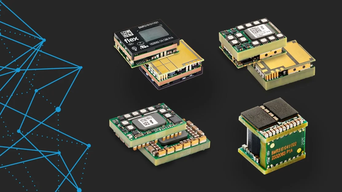
For example, Flex Power Modules offers the BMR316, which is a non-isolated, unregulated IBC with a fixed 4:1 ratio. The BMR316 delivers 1 kW continuous power and 2.8 kW peak power with enhanced efficiency: at an input voltage of 54 V, the efficiency of the module is as high as 97.7% at 50% load.
Alternatively, designers can choose the BMR323, which is another non-isolated, unregulated IBC, but with a fixed ratio of 8:1. Its output voltage ranges from 5 V to 7.5 V, which can help optimize overall system efficiency when used in conjunction with vertical power delivery (VPD) solutions and second-stage VRMs, like the BMR510.
Of course, choosing between a 4:1 and 8:1 IBC is rarely determined by datasheet efficiency curves alone. In high-density AI racks, system-level simulation has become an essential part of architecture selection.
Flex Power Designer, among other software tools, enables power design engineers to model the full embedded power path (48 V → IBC → VRM) and compare 4:1 and 8:1 implementations by analyzing loss distribution, intermediate-bus current density, transient deviation and thermal performance under realistic workload profiles. The software also supports system configuration and efficiency calculation across the entire power chain, including monitoring and control of compatible non-Flex devices via PMBus.
The best conversion ratio is a complex systems-level question, not a simple multiple choice question. Selecting between 4:1 and 8:1 is not about which ratio is “better.”
In both cases, a fixed-ratio IBC is a strong choice to deliver on the efficiency, power density, and reliability required in modern 48 V racks. From there, evaluate how the chosen intermediate bus voltage aligns with transient performance targets, PCB copper losses, thermal density, and the optimization window of the second-stage regulator.
It’s not which approach is better for everyone, it’s which approach is better for you.