Die bevorzugte Lösung besteht darin, einen oder mehrere Zwischenkreise für die Verteilung mit höherer Spannung zu erzeugen, da hier bei gleicher Leistung die ohmschen Verluste geringer sind – beispielsweise 16-mal niedriger bei 48 V im Vergleich zu 12 V, weil der Strom nur ein Viertel beträgt. Anschließend erfolgt die Abwärtswandlung auf die Endspannung mit weiteren DC/DC-Wandlern am Lastpunkt (Point of Load, PoL), Spannungsreglermodulen (VRMs) oder zunehmend integrierten Leistungsstufen (IPSs), die sogenannte intelligente Leistungsstufen mit der erforderlichen Ausgangsinduktivität und weiteren Komponenten kombinieren. Nun müssen Entscheidungen getroffen werden: Welche Busspannung(en) ist/sind optimal? Welche Stufen müssen isoliert und welche Stufen geregelt werden?
Die erste AC/DC-Stufe zur Erzeugung der ersten Rack-Bus-Spannung muss aus Sicherheitsgründen isoliert sein. Danach, bei Spannungen unter 60 V, dient die Isolation aus funktionalen Gründen: Sie verhindert Masseschleifen, reduziert elektromagnetische Störungen und ermöglicht einen starken Spannungsabfall über die Transformatorwindungen. 48 V mit ihren Toleranzen sind daher eine gute Wahl und eine geeignete Versorgungsspannung für die Batterie-Notstromversorgung.
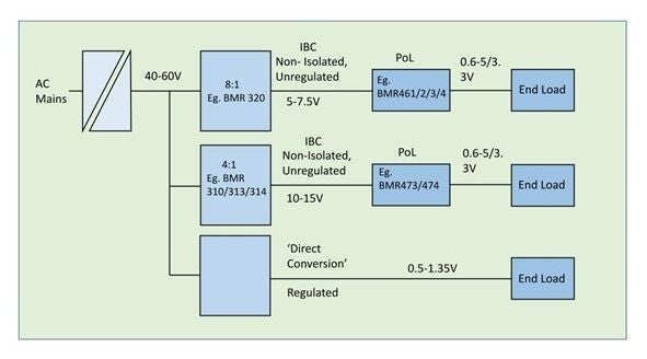
Einige Programme, wie beispielsweise in unserem BMR492 Sie verfügen über ein ‘hybrid geregeltes Verhältnis’ und arbeiten bis zu einer bestimmten Eingangsspannung mit einem festen Verhältnis. Danach greift die Regelung ein, um die Gesamtspannungsschwankung am Ausgang zu begrenzen und gleichzeitig einen hohen Gesamtwirkungsgrad zu gewährleisten. Alternativ können, wenn auf eine Isolation verzichtet wird, hocheffiziente Schaltkondensatoren als IBC (Integrated Breakout Controller) verwendet werden, wie beispielsweise die Leistungsmodule Flex.‘ BMR310, jedoch wiederum beschränkt auf ein festes Verhältnis, das in diesem Fall eine ganze Zahl (4:1) sein muss. Alternativ können nicht isolierte und ungeregelte Bauteile wie beispielsweise Flex-Leistungsmodule verwendet werden.’ BMR313/314, Durch die Verwendung ihrer ‘Resonanz-Gleichstromtransformator (DCX)’-Topologie kann ein Wirkungsgrad von über 97% bei einer Nennleistung von 1 kW und einem Übersetzungsverhältnis von 4:1 erreicht werden.
Glücklicherweise haben Fortschritte in der PoL-Topologie und bei Halbleiterschaltern deren Effizienz auch bei größeren Eingangsspannungsbereichen und hohen Abwärtswandlungsverhältnissen bis hin zu den heute üblichen Sub-1-V-Pegeln verbessert, sodass Systementwickler nun eine größere Auswahl haben. Beispielsweise kann ein IBC mit einem Eingangsspannungsbereich von 40–60 V DC folgende Ausgangsspannungen liefern: 10–15 V DC (4:1), 8–12 V DC (5:1), 6,7–10 V DC (6:1), 5–7,5 V DC (8:1) oder 4–6 V DC (10:1). Höhere IBC-Spannungen können zu geringerem Stromverbrauch und einfacherem Leiterplattenlayout führen, während niedrigere IBC-Spannungen einen effizienteren Betrieb der nachgeschalteten PoLs, VRMs oder IPSs ermöglichen. Diese können dann mit einem Eingangsspannungsbereich ausgewählt werden, der die beste Effizienz für eine gegebene Last bietet. Ein Beispiel für eine solche Kombination wäre ein 400-W-System mit einem Übersetzungsverhältnis von 8:1. BMR320 und die demnächst erscheinende integrierte 16-Phasen-Leistungsstufe BMR515, optimiert für einen Eingangsspannungsbereich von 4,5–7,5 V. Diese Kombination könnte beispielsweise einer GPU bis zu 670 A bei Spannungen von 0,5–0,9 V liefern und auch kurzzeitig Spitzenströme bereitstellen.
Mit weiter steigendem Stromverbrauch der Endgeräte lassen sich Techniken einsetzen, um die Effizienz hoch zu halten. Beispielsweise können mehrphasige PoL-Abwärtswandler über einen breiteren Lastbereich eine optimierte Effizienz aufweisen, und Endgeräte mit besonders hohem Stromverbrauch können über eine eigene ‘Leistungsinsel’ mit einem dedizierten zweistufigen Zwischenbus verfügen, der auf optimale Effizienz ausgelegt ist. Die Effizienz von PoLs lässt sich auch durch MOSFET-Schalter mit minimaler Nennspannung optimieren, da der Einschaltwiderstand bei niedrigeren Nennspannungen – unter sonst gleichen Bedingungen – naturgemäß sinkt. MOSFET-Hersteller haben dies erkannt und bieten zunehmend 15-V-Bauteile an, die mit niedrigeren Busspannungen kompatibel sind und zudem mit höherer Frequenz schalten können. Dadurch werden die Abmessungen von Induktivitäten und Kondensatoren sowie interne Verluste reduziert. Dies schafft Platz auf der Leiterplatte für den Einsatz mehrphasiger PoLs mit ihren eigenen Effizienzgewinnen.
Für eine optimale Gesamtsystemeffizienz ist eine ganzheitliche Betrachtung erforderlich.
In bestimmten Szenarien kann eine Analyse der Effizienz und der erforderlichen Leistung zeigen, dass die ‘direkte Wandlung’ von 48 V auf eine Ausgangsspannung von nur 0,5 V eine höhere Effizienz sowie eine geringere Systemgröße und niedrigere Kosten als die Kombination von IBCs und PoLs, den Flex-Leistungsmodulen, erzielen kann.’ BMR482 ist ein gutes Beispiel.
Die neuesten technologischen Fortschritte bei den Flex Leistungsmodulen haben die Auswahlmöglichkeiten für Systementwickler erweitert. Diese können nun eine ganzheitliche Systembetrachtung vornehmen und entscheiden, wo und ob eine Trennung und Regelung erforderlich sind, um die beste Gesamteffizienz und Funktionalität zu erreichen.