
Blog
Anpassung von IBC-Architekturen an Lastprofile von KI-Rechenzentren
Es scheint noch gar nicht so lange her, da drehten sich Diskussionen über die Leistungsfähigkeit von Rechenzentren um Rechenleistung, Prozessorarchitektur und Netzwerkgröße. Doch da KI die Rack-Dichten in Richtung 1 MW treibt, rückt der Stromverbrauch nun in den Vordergrund. wird beschrieben als Die “neue Währung der Welt”. Ihre Verfügbarkeit, Verwaltung und Umtauscheffizienz müssen nun Schritt halten.
Die IEA neueste Prognose Er geht davon aus, dass der weltweite Stromverbrauch von Rechenzentren von 485 TWh im Jahr 2025 auf rund 950 TWh im Jahr 2030 steigen wird. Im Juni 2026, Die FERC ordnete allen sechs regionalen US-Netzbetreibern an, Es fällt in ihren Zuständigkeitsbereich, die Tarife für den Anschluss großer Verbraucher, darunter Rechenzentren, zu rechtfertigen oder zu reformieren. Kein Wunder also, dass der Zugang zu Strom so stark in den Fokus gerückt ist. Er bestimmt zunehmend, wo neue Rechenzentrumskapazitäten aufgebaut werden können und wie schnell diese in Betrieb genommen werden können.
Die Sicherstellung der Stromversorgung im Rechenzentrum ist eine Herausforderung, die Bereitstellung nutzbarer Leistung für den Prozessor jedoch eine ganz andere. Der Übergang zu 1-MW-Racks und darüber hinaus hat eindeutig ein Umdenken in der Stromversorgungsarchitektur von KI-Rechenzentren erforderlich gemacht. OCPs Diablo Die Spezifikation sieht eine VDC-Lieferung von ±400 aus einem separaten Netzteil vor, während NVIDIA eine breitere Lösung vorschlägt. 800-VDC-Architektur Dies erstreckt sich über die gesamte Stromversorgungskette des Rechenzentrums. Die Spannungen steigen, wodurch Strom- und Widerstandsverluste entlang des Übertragungspfads sinken. Dennoch müssen diese höheren Spannungen sicher und effizient heruntertransformiert werden, zunächst auf einen 48-V-Zwischenbus und dann auf Prozessorspannungen unter 1 V.

Durch den Einsatz von Hochspannungsarchitekturen, die große Leistungsmengen über größere Entfernungen mit geringeren Strömen übertragen, können verschiedene Designentscheidungen getroffen werden, um die Gesamteffizienz zu verbessern. Nicht benötigte Wandlungsstufen werden tendenziell entfernt, sofern die Systemanforderungen dies zulassen, während der Ausgangsspannungsbereich jedes Wandlers typischerweise so optimiert wird, dass er zum Betriebsbereich des nächsten passt.
Das Modul mit dem höchsten im Datenblatt angegebenen Spitzenwirkungsgrad ist jedoch nicht unbedingt die beste Systemwahl. Ein Zwischenkreisumrichter (IBC) mit festem Übersetzungsverhältnis kann geringere Verluste und eine höhere Leistungsdichte bieten, vorausgesetzt, die nachgeschalteten Regler können seine schwankende Ausgangsspannung tolerieren. Ein geregelter IBC hält die Zwischenkreisspannung konstanter, allerdings kann die Regelung zusätzliche Verluste verursachen. Bei gleicher Eingangsspannung und übertragener Leistung erzeugt ein 4:1-IBC eine höhere Zwischenkreisspannung, wodurch der Busstrom und die Leitungsverluste reduziert werden. Ein 8:1-IBC erzeugt eine niedrigere Spannung, was den Zwischenkreisstrom erhöht, aber die erforderliche Abwärtswandlung in der letzten Regelstufe erleichtert. Die optimale Wahl hängt von vielen Faktoren ab, darunter der Eingangsspannungsbereich, das Lastprofil, das Platinenlayout, die Kühlung und der Betriebsbereich der nachgeschalteten Umrichter. Website-Blog Die Wahl zwischen einem Umrechnungsverhältnis von 4:1 und 8:1 wird weiter analysiert.
Die Auslegung jeder Komponente auf eine absolute Spitzenleistung kann die gesamte Leistungskette unnötig überdimensionieren. Die Herausforderung besteht darin, Spitzen- und transiente Lasten zu unterstützen und gleichzeitig übermäßige Auslegungsmargen, Leistungsinstabilität und Leistungsdrosselung zu vermeiden. Leistungsstufen, Regelkreise, Entkopplung und Wärmeleitpfade müssen daher gemeinsam bewertet werden. Leistungsmodule mit klar definierter Spitzenleistungsfähigkeit, Parallelbetrieb und digitaler Steuerung bieten Entwicklern mehr Flexibilität bei der Unterstützung transienter Lasten.
Selbstverständlich ist auch die Kühlung Teil des Stromversorgungsdesigns. Jedes bei der Umwandlung verlorene Watt wird zu Wärme, die aus einem ohnehin schon thermisch begrenzten System abgeführt werden muss. Daher ist es optimal, wenn Kühlung und Stromversorgung von Anfang an gemeinsam geplant werden. Wärmeleitwege auf der Oberseite, Kompatibilität mit Kühlplatten und eine nahe am Prozessor platzierte Stromversorgung können die Querwärme deutlich reduzieren und mehr Leiterplattenfläche freigeben.
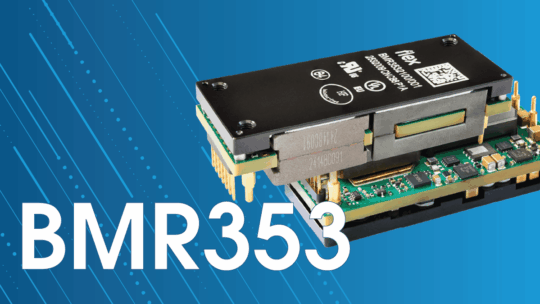
Innerhalb von 48-V-Architekturen können Leistungsentwickler zwischen geregelten und ungeregelten IBCs wählen. Produkte mit festem Übersetzungsverhältnis wie beispielsweise die BMR316 und die BMR321, Mit Umwandlungsverhältnissen von 4:1 bzw. 8:1 bieten sie in Kombination mit nachgeschalteten Stufen, die eine variable Zwischenspannung akzeptieren, eine hohe Umwandlungseffizienz und Leistungsdichte. Im Gegensatz dazu bietet ein geregelter Viertel-Brick-Wandler wie der BMR352 Das System hält die Nennspannung von 12 V konstant, auch bei schwankender Eingangsspannung. Bei Bedarf an höherer Ausgangsleistung unterstützt es zudem die Parallelschaltung durch aktive Stromverteilung. Die Module können kurzzeitige Lastspitzen oberhalb ihrer Dauernennleistung bewältigen, sofern Dauer und Wiederholungsrate innerhalb der vorgegebenen Grenzen bleiben und die erforderliche Kühlung gewährleistet ist.
Für KI-Stromversorgungssysteme der nächsten Generation mit 800 VDC oder ±400 VDC ist zunächst eine effiziente Wandlungsstufe erforderlich, die die Hochspannung innerhalb des Racks sicher heruntertransformiert und dabei Isolation und Schutz auf Systemebene definiert. Wir entwickeln DC/DC-Leistungsmodule für beide Architekturen, beispielsweise den BMR720. Ursprünglich für ±400 VDC-Systeme konzipiert, wandelt der BMR720 die Spannung auf einen 50-V-Bus um und liefert bis zu 10 kW Dauerleistung bzw. 15 kW Spitzenleistung. Dies ermöglicht den Übergang von neuen Anlagen- und Rackstandards in die für Serverhardware benötigten Niederspannungsbereiche, ohne dass jeder Kunde einen Hochspannungswandler von Grund auf neu entwickeln muss.
In der Nähe des Prozessors befinden sich Spannungsreglermodule und vertikale Stromversorgung (VPD) werden immer wichtiger. Lösungen wie die BMR510 Sie können hohe Ströme bei Ausgangsspannungen bis hinunter zu 0,5 V liefern, während kundenspezifische VPD-Lösungen die letzte Wandlungsstufe direkt unter dem Prozessor platzieren. Dies verkürzt den Hochstrompfad, reduziert Widerstandsverluste und verbessert das Einschwingverhalten, während gleichzeitig wertvolle Leiterplattenfläche frei wird. Diese Vorteile gewinnen mit steigendem Prozessorstrom zunehmend an Bedeutung.
Wie bereits erwähnt, ist das Produkt nur ein Teil der Stromversorgungslösung. Digitale Schnittstellen wie PMBus ermöglichen den Zugriff auf Betriebsdaten, unterstützen die Konfiguration und helfen Ingenieuren, Fehler oder das Lastverhalten zu verstehen. Flex Power Designer, ein branchenführendes Softwaretool zur Analyse der Leistungsfähigkeit von Stromversorgungssystemen unter realen Betriebsbedingungen, ermöglicht es Teams, ein komplettes digitales Stromversorgungssystem zu modellieren, bevor sie sich für Hardware entscheiden. Dabei lassen sich Wirkungsgrad, thermisches Verhalten, Phasenausbreitung und Droop-Verhalten unter erwarteten Bedingungen vergleichen. Evaluierungsboards und Anwendungsentwicklung ermöglichen anschließend die Überprüfung dieser Annahmen, bevor das Design die endgültige Plattform erreicht.
Für jedes von einer Umwandlungsstufe verarbeitete MW entspricht jeder Prozentpunkt Verlust etwa 10 kW Wärme. Durch die Reduzierung dieser Verluste sinkt die benötigte Eingangsleistung, um die gleiche Leistung an die Prozessoren zu liefern, und die Kühlung wird erleichtert. Zudem kann die thermische Belastung innerhalb der Stromversorgungskette verringert werden, wodurch mehr der festen Leistungskapazität für Rechenprozesse zur Verfügung steht. Über mehrere Racks und Umwandlungsstufen hinweg vervielfachen sich diese Einsparungen.
In einem Rechenzentrum mit begrenzter Energieversorgung ist eine hohe Umwandlungseffizienz unerlässlich. Zusätzliche Erzeugungskapazität und eine höhere Netzkapazität sind weiterhin notwendig, benötigen jedoch Zeit und hängen von Faktoren außerhalb des Racks ab. Die Reduzierung der Verluste zwischen Netz und Chip bietet eine kurzfristigere Möglichkeit, mehr der verfügbaren Leistung des Standorts den Prozessoren zur Verfügung zu stellen.
Energie ist die neue Währung der KI-Infrastruktur. Effiziente Bereitstellung und Umwandlung sind daher ein Wettbewerbsvorteil und eine wirtschaftliche Notwendigkeit. Unternehmen, die eingebettete Energieversorgung und Rechenleistung als ein komplettes System entwickeln, sind besser positioniert, um jedes knappe Megawatt in zuverlässige KI-Kapazität umzuwandeln.